Goal V18: Difference between revisions
m (→Gallery: Tweak captions, remove links) |
m (→Gallery: <div align="center">) |
||
| (32 intermediate revisions by 3 users not shown) | |||
| Line 1: | Line 1: | ||
= | <span style="font-size:22px">GOAL V18</span> | ||
---- | |||
{{Lock model | {{Lock model | ||
| name = GOAL V18 | | name = GOAL V18 | ||
| Img = File:Goal_V18_housing_keyway_-_FXE47506.jpg | | Img = File:Goal_V18_housing_keyway_-_FXE47506.jpg | ||
| Img_size = | | Img_size = 200px | ||
| maker = [[Goal |GOAL]] | | maker = [[Goal |GOAL]] | ||
| lock_type = [[Cylinder]] | | lock_type = [[Cylinder]] | ||
| lock_design = [[Pin_tumbler|Pin-tumbler]], [[Dimple]] | | lock_design = [[Pin_tumbler|Pin-tumbler]], [[Dimple]] | ||
| ratings = [[UL 437]] | |||
| years_produced = | | years_produced = | ||
| patent = | | patent = | ||
| related = [[Goal D9 |GOAL D9]] | | related = [[Goal D9 |GOAL D9]] | ||
| spec_on = yes | | spec_on = yes | ||
| spec_comptype = Pin-tumbler | | spec_comptype = [[Pin_tumbler|Pin-tumbler]] | ||
| spec_comp = | | spec_comp = 19 | ||
}} | }} | ||
__TOC__ | __TOC__ | ||
<br | <br> | ||
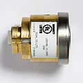
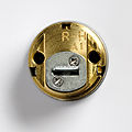
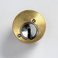
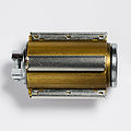
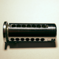
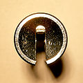
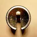
The '''V18''' is a [[dimple]] lock made by [[Goal|GOAL]]. Drilled for 21 pins, it contains up to 19 active pins and two core-centering pins. Pins are arranged in rows of seven on the left, top, and right of the keyway. | The '''V18''' is a [[dimple]] lock made by [[Goal|GOAL]]. Drilled for 21 pins, it contains up to 19 active pins and two core-centering pins. Pins are arranged in rows of seven on the left, top, and right of the keyway. | ||
'' '''Please note:''' the V18 is very similar to the GOAL GP and the smaller, nine-pin [[Goal D9 |GOAL D9]] model. The locks share the same pins, fundamental designs, and primary security features.'' | |||
== Principles of operation == | == Principles of operation == | ||
[[Image:Goal V18-03 all pins - FXE47613.jpg|right|thumb|255px|V18 full pin set]] | |||
[[Image:Goal V18 pin stack variations - FXE47726.jpg|right|thumb|255px|V18 pin stacks: standard, click bearing, dummy pins for master keying]] | |||
<!--[[Image:Goal V18 core with bearing - FXE47712-Edit.jpg|right|thumb|255px|V18 click bearing, concave key pin]]--> | |||
GOAL utilizes a | The [[Goal|GOAL]] V18 utilizes [[dimple]] keys but functions the same as a standard [[Pin_tumbler |pin-tumbler]] lock. The lock uses 21 chambers for pin-tumbler stacks. Up to nineteen of those chambers each contain a set of key pin, driver, and spring. The dimple key of the V18 has four cut depths for side pins and three, different cut depths for pins in the top row. The design offers 12 billion [[Differs|key differences]] when pinned with 18 active pins. The key is bitted on the sides and edges of the blade and is reversible. To open the lock, all active pin-tumblers -- across all three rows of pins -- must be aligned at the [[shear line]]. ''(See also [[Pin_tumbler#Principles_of_operation|Pin-tumbler, Principles of operation]])'' | ||
The V18 uses a mix of thin and thick lipped mushroom spool drivers. Drivers are cupped to allow the spring to nest inside the pins. Key pins are a combination of t-pins and multi-section tapered spools which are torpedo shaped to create overset traps. These pin designs match overmilling of the pin chambers in the core to catch pins as they are lifted to shear. The top row of pin chambers in the bible is taller than the side rows in larger models of the V18. Brass spacer pins are placed above the spring to match the increase length of the pin chambers. | GOAL utilizes a variety of [[security pin]]s to deter picking. Active pin stacks incorporate seven total lengths of stainless steel key pins with two sizes of steel driver pins to match. The V18 uses a mix of thin and thick lipped mushroom spool drivers. Drivers are cupped to allow the spring to nest inside the pins. Key pins are a combination of t-pins and multi-section tapered spools which are torpedo shaped to create overset traps. These pin designs match overmilling of the pin chambers in the core to catch pins as they are lifted to shear. The top row of pin chambers in the bible is taller than the side rows in larger models of the V18. Brass spacer pins are placed above the spring to match the increase length of the pin chambers. | ||
{| class="wikitable" | |||
!colspan="5"| V18 pin sizes (mm) | |||
|- | |||
| Top row pins || 4.20 || 4.75 || 5.20 || | |||
|- | |||
| Side row pins || 5.15 || 5.65 || 6.15 || 6.50 | |||
|} | |||
Two of the chambers, one on each side, contain a sprung bearing or "click ball" to bias the core. This core-centering mechanism consists of a pin with a concave top which sits in the core without entering the keyway and a ball bearing which sits in the bible. This click device acts as a detent when the key aligns the core to the locked position. <!-- when a key is present in the lock --> Centering pin stacks are also distinguishable by their shorter and wider springs. The core-biasing bearings are always located one each on the left and right side of the lock, but the location within each row can vary. | Two of the chambers, one on each side, contain a sprung bearing or "click ball" to bias the core. This core-centering mechanism consists of a pin with a concave top which sits in the core without entering the keyway and a ball bearing which sits in the bible. This click device acts as a detent when the key aligns the core to the locked position. <!-- when a key is present in the lock --> Centering pin stacks are also distinguishable by their shorter and wider springs. The core-biasing bearings are always located one each on the left and right side of the lock, but the location within each row can vary. | ||
| Line 33: | Line 45: | ||
Additionally, the V18 uses two, smaller "ward pins" to restrict access to the keyway. These pins are situated in holes in the core and do not interact with the bitting of the key. | Additionally, the V18 uses two, smaller "ward pins" to restrict access to the keyway. These pins are situated in holes in the core and do not interact with the bitting of the key. | ||
[[Master keying]] the V18 involves strategically removing one or more pins to create one or more mastered versions. <!--[what is the correct term?]--> GOAL uses inactive, dummy key pins and drivers made of brass. They take the place of active pin stacks and do not interact with the key. Master key systems thus reduce the number of active pins. | [[Master_key |Master keying]] the V18 involves strategically removing one or more pins to create one or more mastered versions. <!--[what is the correct term?]--> GOAL uses inactive, dummy key pins and drivers made of brass. They take the place of active pin stacks and do not interact with the key. Master key systems thus reduce the number of active pins. | ||
== Model variations == | == Model variations == | ||
[[Image:Goal V18 rim v compact - FXE47636.jpg|right|thumb| | [[Image:Goal V18 rim v compact - FXE47636.jpg|right|thumb|255px|Comparison of V18 compact and standard cylinders]] | ||
Two V18 cylinders are shown here: | Two V18 cylinders are shown here: | ||
| Line 50: | Line 57: | ||
The V18 system is available in a [[UL 437]] rated cylinder. | The V18 system is available in a [[UL 437]] rated cylinder. | ||
== Disassembly instructions == | |||
The GOAL V18 is disassembled in the same way as a traditional pin-tumbler cylinder. | |||
# Remove the rear plate (standard cylinder) or C-clip (compact cylinder) | |||
# Insert the key and turn the [[plug]] 30-45 degrees. | |||
# Withdraw the plug from the cylinder. (A [[plug follower]] and [[Plug_follower#Core_shim |core shims]] are strongly recommended) | |||
:''Note: the three bible covers of the compact cylinder can be removed easily and non-destructively.'' | |||
:''This makes gutting and re-pinning possible without removing the plug.'' | |||
<br clear="all"> | <br clear="all"> | ||
== Gallery == | == Gallery == | ||
<gallery align="center"> | <div align="center"><gallery align="center"> | ||
File:Goal V18 cylinder front - FXE47507.jpg | Front view of a GOAL V18 rim cylinder | File:Goal V18 cylinder front - FXE47507.jpg | Front view of a GOAL V18 rim cylinder | ||
File:Goal_V18_cylinder_top_-_FXE47513.jpg |Exterior of a V18 rim cylinder | File:Goal_V18_cylinder_top_-_FXE47513.jpg |Exterior of a V18 rim cylinder | ||
| Line 60: | Line 79: | ||
File:Goal_V18_small_cylinder_-_FXE47493.jpg |Exterior of a V18 compact cylinder | File:Goal_V18_small_cylinder_-_FXE47493.jpg |Exterior of a V18 compact cylinder | ||
File:GOALv18_cylinder_key_color-Reinder.png|A V18 cylinder and key | File:GOALv18_cylinder_key_color-Reinder.png|A V18 cylinder and key | ||
File:GOALv18_key_cuts_01_edit-Reinder.jpg |V18 key, showing dimple cuts | |||
File:Goal_V18_key_-_FXE47497.jpg |A V18 key | File:Goal_V18_key_-_FXE47497.jpg |A V18 key | ||
File:Goal-V18-D9-size-compare.jpg |Key & cylinder of the V18 with that of a [[Goal D9|GOAL D9]] | File:Goal-V18-D9-size-compare.jpg |Key & cylinder of the V18 with that of a [[Goal D9|GOAL D9]] | ||
File:Goal V18 core - FXE47697.jpg | V18 core | File:Goal V18 core - FXE47697.jpg | V18 core with overmilling & narrowing chambers | ||
File:Goal V18 pin sizes - FXE47722.jpg | V18 pin sizes | File:Goal V18 pin sizes - FXE47722.jpg | V18 pin sizes | ||
File:V18 side pins new - FXE47612.jpg | Side pins | File:V18 side pins new - FXE47612.jpg | Side pins | ||
| Line 71: | Line 89: | ||
File:Goal V18 pin stack variations - FXE47726.jpg | Pin stack variations | File:Goal V18 pin stack variations - FXE47726.jpg | Pin stack variations | ||
File:Goal V18-03 all pins - FXE47613.jpg | V18 all pins | |||
File:GOALv18_pins_01_edit-Reinder.jpg|Pins and springs from a V18 | |||
File:GOALv18_concave_click_pin-Reinder.png |The concave surface of a V18 click pin | |||
File:Goal V18 core with bearing - FXE47712-Edit.jpg | V18 core with bearing | File:Goal V18 core with bearing - FXE47712-Edit.jpg | V18 core with bearing | ||
File:Goal V18 ward pins - FXE47665-Edit-Edit.jpg | V18 ward pins | File:Goal V18 ward pins - FXE47665-Edit-Edit.jpg | V18 ward pins | ||
File:Goal_V18-05_front_-_lit_glowing_-_FXE47828.jpg | V18 keyway, glow-in-the-dark | |||
<!-- File:GOALv18_tray_of_pins_edit-Reinder.jpg|Pins and springs. --> | <!-- File:GOALv18_tray_of_pins_edit-Reinder.jpg|Pins and springs. --> | ||
File:GOALv18_plug_chambers_top-Reinder.png |Pin chambers in a V18 plug, narrowing at the bottom | |||
File:GOALv18_plug_01_color-Reinder.png|Right side of a V18 plug | File:GOALv18_plug_01_color-Reinder.png|Right side of a V18 plug | ||
File:GOALv18_plug_bottom-Reinder.png|Bottom of a V18 plug | File:GOALv18_plug_bottom-Reinder.png|Bottom of a V18 plug | ||
File:GOALv18_plug_top-Reinder.png |Top of a V18 plug | File:GOALv18_plug_top-Reinder.png |Top of a V18 plug | ||
File:GOALv18_plug_chambers_top-Reinder.png |Pin chambers in a V18 plug, top row | <!-- File:GOALv18_plug_chambers_top-Reinder.png |Pin chambers in a V18 plug, top row *DUPLICATE* --> | ||
File:GOALv18_plug_03_edit-Reinder.jpg|Keyway without "warding" pins | File:GOALv18_plug_03_edit-Reinder.jpg|Keyway without "warding" pins | ||
File:GOALv18_plug_04_edit-Reinder.jpg|Keyway with "warding" pins | File:GOALv18_plug_04_edit-Reinder.jpg|Keyway with "warding" pins | ||
File:GOALv18_ward_pins_edit-Reinder.jpg|Ward pins | File:GOALv18_ward_pins_edit-Reinder.jpg|Ward pins | ||
File:Goal_V18_keyway_wrench-Reinder.jpg |Two tension tools combined to fit the wide keyway of the V18 | File:Goal_V18_keyway_wrench-Reinder.jpg |Two tension tools combined to fit the wide keyway of the V18 | ||
</gallery> | </gallery></div> | ||
== See also == | == See also == | ||
* [[Dimple | * [[Goal|GOAL]] | ||
* [[ | * [[Dimple|Dimple locks]] | ||
* [[:Category:Lock_models|List of lock model articles]] | |||
[[Category:Lock models]] | [[Category:Lock models]] | ||
[[Category:Goal]] | |||
[[Category:Dimple_locks]] | [[Category:Dimple_locks]] | ||
[[Category:Pin-tumbler_locks]] | [[Category:Pin-tumbler_locks]] | ||
[[Category:UL_437_locks]] | [[Category:UL_437_locks]] | ||
Latest revision as of 14:10, 2 February 2023
GOAL V18
| GOAL V18 | |
 | |
| Name | GOAL V18 |
|---|---|
| Manufacturer | GOAL |
| Lock Type | Cylinder |
| Lock Design | Pin-tumbler, Dimple |
| Security Rating(s) | UL 437 |
| Specifications | |
| # of Components | 19 |
| Component Type | Pin-tumbler |
| Related Locks | |
| GOAL D9 | |
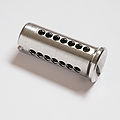
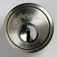
The V18 is a dimple lock made by GOAL. Drilled for 21 pins, it contains up to 19 active pins and two core-centering pins. Pins are arranged in rows of seven on the left, top, and right of the keyway.
Please note: the V18 is very similar to the GOAL GP and the smaller, nine-pin GOAL D9 model. The locks share the same pins, fundamental designs, and primary security features.
Principles of operation
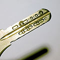
The GOAL V18 utilizes dimple keys but functions the same as a standard pin-tumbler lock. The lock uses 21 chambers for pin-tumbler stacks. Up to nineteen of those chambers each contain a set of key pin, driver, and spring. The dimple key of the V18 has four cut depths for side pins and three, different cut depths for pins in the top row. The design offers 12 billion key differences when pinned with 18 active pins. The key is bitted on the sides and edges of the blade and is reversible. To open the lock, all active pin-tumblers -- across all three rows of pins -- must be aligned at the shear line. (See also Pin-tumbler, Principles of operation)
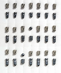
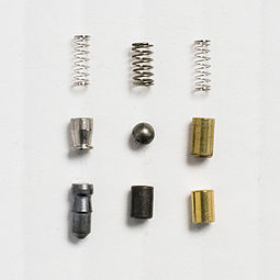
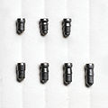
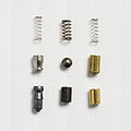
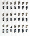
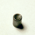
GOAL utilizes a variety of security pins to deter picking. Active pin stacks incorporate seven total lengths of stainless steel key pins with two sizes of steel driver pins to match. The V18 uses a mix of thin and thick lipped mushroom spool drivers. Drivers are cupped to allow the spring to nest inside the pins. Key pins are a combination of t-pins and multi-section tapered spools which are torpedo shaped to create overset traps. These pin designs match overmilling of the pin chambers in the core to catch pins as they are lifted to shear. The top row of pin chambers in the bible is taller than the side rows in larger models of the V18. Brass spacer pins are placed above the spring to match the increase length of the pin chambers.
| V18 pin sizes (mm) | ||||
|---|---|---|---|---|
| Top row pins | 4.20 | 4.75 | 5.20 | |
| Side row pins | 5.15 | 5.65 | 6.15 | 6.50 |
Two of the chambers, one on each side, contain a sprung bearing or "click ball" to bias the core. This core-centering mechanism consists of a pin with a concave top which sits in the core without entering the keyway and a ball bearing which sits in the bible. This click device acts as a detent when the key aligns the core to the locked position. Centering pin stacks are also distinguishable by their shorter and wider springs. The core-biasing bearings are always located one each on the left and right side of the lock, but the location within each row can vary.
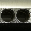
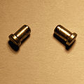
Additionally, the V18 uses two, smaller "ward pins" to restrict access to the keyway. These pins are situated in holes in the core and do not interact with the bitting of the key.
Master keying the V18 involves strategically removing one or more pins to create one or more mastered versions. GOAL uses inactive, dummy key pins and drivers made of brass. They take the place of active pin stacks and do not interact with the key. Master key systems thus reduce the number of active pins.
Model variations
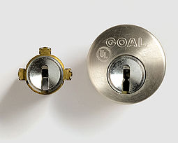
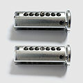
Two V18 cylinders are shown here:
- A standard cylinder, model V-LX 5
- A compact cylinder, V-TX
Both utilize the same components and general security features. The rim cylinder is larger, more robust, and incorporates steel ball bearings for drill protection. The compact cylinder features easy-to-remove bible covers and is much easier to re-pin.
The V18 system is available in a UL 437 rated cylinder.
Disassembly instructions
The GOAL V18 is disassembled in the same way as a traditional pin-tumbler cylinder.
- Remove the rear plate (standard cylinder) or C-clip (compact cylinder)
- Insert the key and turn the plug 30-45 degrees.
- Withdraw the plug from the cylinder. (A plug follower and core shims are strongly recommended)
- Note: the three bible covers of the compact cylinder can be removed easily and non-destructively.
- This makes gutting and re-pinning possible without removing the plug.
Gallery
Key & cylinder of the V18 with that of a GOAL D9
