MIWA JN: Difference between revisions
m (→Gallery: add core side view) |
m (additional feature image) |
||
| Line 16: | Line 16: | ||
}} | }} | ||
__TOC__ | __TOC__ | ||
[[Image:MIWA JN pin axes - MIWA JN four pin axes.png|right|thumb|255px|MIWA JN four pin axes]] | |||
The '''JN''' is a [[dimple]] lock made by the Japanese manufacturer [[MIWA]]. Drilled for 21 pins, it is often filled with fewer active pins. Pins are arranged in four rows to the left side of the keyway, the right side and two diagonal rows milled 45 deg. from the bottom of lock. | The '''JN''' is a [[dimple]] lock made by the Japanese manufacturer [[MIWA]]. Drilled for 21 pins, it is often filled with fewer active pins. Pins are arranged in four rows to the left side of the keyway, the right side and two diagonal rows milled 45 deg. from the bottom of lock. | ||
Latest revision as of 14:13, 2 February 2023
MIWA JN
| MIWA JN | |
 | |
| Name | MIWA JN |
|---|---|
| Manufacturer | MIWA |
| Lock Type | Cylinder |
| Lock Design | Pin-tumbler, Dimple |
| Specifications | |
| # of Components | up to 21 |
| Component Type | Pin-tumbler |
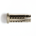
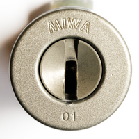
The JN is a dimple lock made by the Japanese manufacturer MIWA. Drilled for 21 pins, it is often filled with fewer active pins. Pins are arranged in four rows to the left side of the keyway, the right side and two diagonal rows milled 45 deg. from the bottom of lock.
Principles of operation
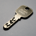
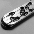
The MIWA JN utilizes dimple keys but functions the same as a standard pin-tumbler lock. The dimple key of the JN has four cut depths for the two rows of side pins and two, different cut depths for pins in the two diagonal rows. The key is bitted on the sides and edges of the blade and is reversible. To open the lock, all active pin-tumblers -- across all four rows of pins -- must be aligned at the shear line. (See also Pin-tumbler, Principles of operation).
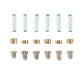
The lock contains up 21 chambers for pin-tumbler stacks. At most, it is drilled for six pins in the right-hand side row of pins and five in each of the other rows. It is common for the lock to contain fewer than 21 pins. In that case the core, housing, and key may only be milled for the active pins. Each active chamber contains a set of key pin, driver, and spring.
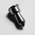
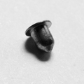
MIWA utilizes a variety of security pins to deter picking. Active pin stacks incorporate six total lengths of stainless steel key pins with several sizes of steel and brass driver pins to match. The JN uses standard driver pins which are cupped to allow the spring to nest inside the pins. Key pins are a combination of t-pins and multi-section tapered spools which are torpedo shaped to create overset traps.
There is no counter- or over-milling in the core. The lock does not contain bearings for centering the core nor does it house any additional mechanisms for drill protection.
Disassembly instructions
Disassembly may vary by cylinder type. For the most common Japanese RIM cylinder the cylinder must first be removed from it's outer housing. It is kept in place by a single C-clip and positioned by washers in the outer housing. Care should be taken to preserve the order of these washers and internal components while disassembling.
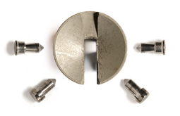
The lock cylinder itself can be disassembled by removing the c-clip retaining the core and gutting the lock using a plug follower. Pins and springs can also be removed by sliding out each of the four bible covers holding them in the lock.
Gallery
See also
| This article is a stub. You can help Lockwiki by expanding it. |
