ASSA Twin V-10: Difference between revisions
m (→See also: assa category listing) |
m (→Gallery: added image of pin kit) |
||
| Line 63: | Line 63: | ||
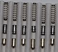
File:ASSA_Twin_V10_all_pins.jpg|Pins and springs used in the V-10 system. | File:ASSA_Twin_V10_all_pins.jpg|Pins and springs used in the V-10 system. | ||
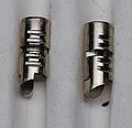
File:ASSA_Twin_V10_counter_milling.jpg|Counter milling in the plug chambers provides manipulation resistance. | File:ASSA_Twin_V10_counter_milling.jpg|Counter milling in the plug chambers provides manipulation resistance. | ||
File:PK-MM_Open_Cen_2_21.png| ASSA Twin V-10 mini pin kit. | |||
</gallery></div> | </gallery></div> | ||
Revision as of 13:21, 27 June 2021
ASSA Twin V-10 (7000)
| ASSA Twin V-10 | |
 | |
| Name | ASSA Twin V-10 |
|---|---|
| Manufacturer | ASSA |
| Lock Type | Cylinder |
| Lock Design | Pin-tumbler, Sidebar |
| Year(s) Produced | 1996-present[1] |
| Patent | US 5,067,335 |
| Related Locks | |
| ASSA Twin 6000 ASSA Twin Combi ASSA Twin Exclusive ASSA Twin Maximum ASSA Twin Pro | |
The Twin V-10 (or V-10, Twin 2, Twin 7000) is a UL 437 rated pin-tumbler lock made by ASSA. The V-10 is part of the Twin series of locks that use pin-tumblers and a sidebar to provide two layers of security. The V-10 is an updated version of the ASSA Twin 6000 cylinder.
The V-10 is distinct because it is the first of the Twin series to provide geographically distributed sidebar codes to protect against key interchange and unauthorized duplication. It also has a patented key control system that provides a high number of key and sidebar differs.
Principles of operation
The V-10 uses six pin-tumblers and five sidebar finger pins. The top (driver) pins use single and double-spool designs. Counter-milling in the plug chambers works with the spool pins and provides a high level of pick resistance. There are 9 depths available for bottom (key) pins, and four depths available for top (driver) pins. Top and bottom pins are combined to provide a uniform height pin stack that resists attack from comb picks as well as reduces wear on the springs. In total, there are 531,441 (96) theoretical key differs for the pin-tumbler portion of the lock.
The sidebar, located in the 8 o'clock position, is pushed out by two springs. The sidebar is interesting because it provides a pre-made set of cuts that must be matched by the finger pins. This contrasts traditional sidebars which have uniform sidebar cuts. In the V-10 system, all finger pins have the same true gates and the key raises them to different positions to match the sidebar. Manipulation protection on the finger pins is provided in the form of false gates above and below the true gate. V-10 finger pins can also be in either the for (left) or aft (right) positions. Mono-keyed locks all use the for position, but master key systems include both for and aft positions. Finger pins can be lifted to five different positions. In total, there are 100,000 ((5*2)5) sidebar bittings (3,125 in mono-keyed systems).
The cylinder and plug use a variety of hardened steel inserts to protect against forced entry. In the plug, steel rods are located at the 9, 12, and 3 o'clock positions. In the cylinder, three rods are located in front of the pin chambers at the 12 o'clock position. Rods near the third pin chamber in the plug and cylinder are also common.
Notes
- The patent on V-10 key profiles ends in December, 2014.[2]
- Older V-10 keys list the direct keyway code on the bow of the key. Newer keys use an indirect code.
- The pin-tumbler bitting code is referred to as the system code, and the sidebar bitting code as the sidebar code.
Disassembly instructions
The V-10 is disassembled in the same way as a traditional pin-tumbler cylinder. The sidebar does not cause too many problems when the plug is removed. When the key is removed from the exposed plug the finger pins will be forced out by spring pressure.
- Remove the cam or C-clip.
- Insert the key and turn the plug 45-90 degrees.
- Withdraw the plug from the cylinder. (A plug follower is recommended)
OR
- Remove the chamber casings and take out each pin-stack individually
- Remove the cam or C-clip.
- Withdraw the plug from the cylinder.
Vulnerabilities
The V-10 system may be vulnerable to one or more of the following:
Notes
- Bumping is possible given a bump key with the correct sidebar bitting. This was a cause for concern when bumping became popular because of the poor distribution of regional sidebar codes in the V-10 system.


