American Lock 1100 1200 1300
American Lock 1100, 1200, 1300
| American Lock 1100, 1200, 1300 | |
 | |
| Name | American Lock 1100, 1200, 1300 |
|---|---|
| Manufacturer | American Lock |
| Lock Type | Padlock, Cylinder |
| Lock Design | Pin-tumbler |
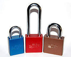
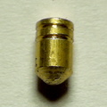
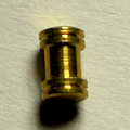
The 1100, 1200, and 1300 series are rekeyable pin-tumbler padlocks made by American Lock. These padlocks are anodized aluminum and come in a variety of colors. These padlocks are among the most common American brand padlocks found in the United States. They are sometimes used in environments where a spark-resistant material is required, such as firearm magazines, making them a popular choice for lock-out padlocks. The cylinders contain serrated keypins, as well as serrated and serrated-spool drivers, offering some resistance to lockpicking.
Padlock Series
The series number stamped on the back of the padlock identifies the lock body size, the factory-supplied shackle length and the number of pins.
| Model | Body Width | Shackle Diameter | Shackle Length | Pins |
|---|---|---|---|---|
| A1105 | 38mm / 1.5" | 6mm / 0.25" (1/4") | 25mm / 1" | 5 |
| A1165 | 38mm / 1.5" | 6mm / 0.25" | 25mm / 1" | 6 |
| A1106 | 38mm / 1.5" | 6mm / 0.25" | 38mm / 1.5" | 5 |
| A1166 | 38mm / 1.5" | 6mm / 0.25" | 38mm / 1.5" | 6 |
| A1107 | 38mm / 1.5" | 6mm / 0.25" | 75mm / 3" | 5 |
| A1167 | 38mm / 1.5" | 6mm / 0.25" | 75mm / 3" | 6 |
| A1205 | 44mm / 1.75" | 8mm / 0.3" (5/16") | 29mm / 1.125" (1-1/8") | 5 |
| A1265 | 44mm / 1.75" | 8mm / 0.3" | 29mm / 1.125" | 6 |
| A1206 | 44mm / 1.75" | 8mm / 0.3" | 51mm / 2" | 5 |
| A1266 | 44mm / 1.75" | 8mm / 0.3" | 51mm / 2" | 6 |
| A1207 | 44mm / 1.75" | 8mm / 0.3" | 75mm / 3" | 5 |
| A1267 | 44mm / 1.75" | 8mm / 0.3" | 75mm / 3" | 6 |
| A1305 | 50mm / 2" | 9.5mm / 0.375" (3/8") | 29mm / 1.125" (1-1/8") | 5 |
| A1365 | 50mm / 2" | 9.5mm / 0.375" | 29mm / 1.125" | 6 |
| A1306 | 50mm / 2" | 9.5mm / 0.375" | 51mm / 2" | 5 |
| A1366 | 50mm / 2" | 9.5mm / 0.375" | 51mm / 2" | 6 |
| A1307 | 50mm / 2" | 9.5mm / 0.375" | 75mm / 3" | 5 |
| A1367 | 50mm / 2" | 9.5mm / 0.375" | 75mm / 3" | 6 |
Note that while 6-pin models (with a "6" in the second last position of the model number) utilize the APTC14 cylinders, the APTC12 "5 pin" cylinders are in fact drilled for 6 pins already and can be easily converted by simply adding a 6th pin, driver and spring.
Date Stamp
Like most American locks, 1100, 1200 and 1300 series are stamped with a date code. The code method changed sometime around 2013. Locks made after the change have a 4 digit date number (3 digit day of the year, eg. 042 is the 42nd day, and a 1 digit year, eg. 8 is 2018) followed by a 2 letter machine/operator code. Locks made before the change start with three letters which are decoded below. This information was taken from the American Lock Service Manual[1][2].
| Jan | Feb | Mar | Apr | May | Jun | Jul | Aug | Sep | Oct | Nov | Dec |
|---|---|---|---|---|---|---|---|---|---|---|---|
| Z | Y | X | W | V | U | T | S | R | Q | P | O |
| 1 | 2 | 3 | 4 | 5 | 6 | 7 | 8 | 9 | 0 |
|---|---|---|---|---|---|---|---|---|---|
| N | M | L | K | J | I | H | G | F | E |
Note: Only the first three characters stamped on the lock body are part of the date code. The meaning of any additional characters is unknown.
Available Colors
| Color | Order Code |
|---|---|
| Black | BLK |
| Blue | BLU |
| Brown | BRN |
| Yellow | YLW |
| Red | RED |
| Green | GRN |
| Orange | ORJ |
| Purple | PRP |
| Clear | CLR |
Lock Options
A weatherproof cover is available for the 1200 and 1300 (but not the 1100) padlocks. Other options, such as a sash chain, bump-stop cylinder, brass shackle (for high corrosion or spark sensitive environments), laser engraving and alternate cylinders are also available by special order from the manufacturer.
Bypass Restriction Plate
In newer American Lock padlocks, a bypass restriction plate has been added which prevents the manipulation of the actuator cam with a special tool through the keyway. The plate takes the form of a circular metal disc with a half-moon cutout in it that fits over the actuator. When servicing older padlocks that do not have this plate, it is advisable to install them to address this simple but serious security vulnerability.
Disassembly instructions
Unlock the padlock and swivel the shackle out of the way, revealing the cylinder retaining screw. Remove this screw, which will release the trap plate at the bottom of the lock and permit the cylinder to be removed.
To further disassemble the padlock: with the retaining screw, trap plate, retaining nut and cylinder removed; carefully lock the padlock while keeping the shackle depressed. Unless the lock is dirty inside, this will generally cause the actuator and ball bearings to drop out the bottom of the lock. If they don't drop out immediately, gently tap the lock against a hard surface to dislodge the parts. Then, remove the shackle and shackle spring.
Reassembly instructions
Reassembly is done in reverse order: After cleaning the disassembled padlock, insert the shackle spring and shackle. Invert the padlock while holding the shackle in place, and insert the locking balls with some grease, followed by the actuator. Next install the anti-bypass plate (optional), the cylinder, trap door and nut. Before installing the retaining screw, test the padlock by holding the trap door and nut in place (the nut is necessary to allow proper cylinder operation) by locking and unlocking the padlock several times. When you are confident the lock is operating correctly, install the retaining screw.
Cylinder compatible locks
Other American padlocks that utilize the same cylinders (APTC12 or APTC14) include:
Additionally, the ABUS 34/55 and 34CS/55 as well as the ABUS 72 series padlocks also accept these cylinders.


