ASSA 700
From Lockwiki
Jump to navigationJump to search
ASSA 700
| ASSA 700 | |
 | |
| Name | ASSA 700 |
|---|---|
| Manufacturer | ASSA |
| Lock Type | Cylinder |
| Lock Design | Pin-tumbler |
| Year(s) Produced | 1948- |
| Specifications | |
| # of Components | 7 |
| Component Type | Pin-tumbler |
| Related Locks | |
| ASSA d12 | |
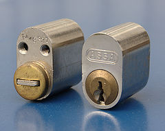
The 700 is a series of pin-tumbler locks made by ASSA. 700 cylinders are designed for domestic environments with high use.
Principles of Operation
- See also: Pin-tumbler (Principles of operation)
700 cylinders feature a single shear line. All models have seven pin stacks and use security pins. Cylinders are available in mortise, rim, and Scandinavian profiles and can be fitted in specialized padlock housings. The "SCD" stamp indicates that it is "Security Cylinder Drillproof". Keys for the 700 are nickel silver. The key combination is read from tip to bow. A #1 cut is the deepest and a #9 cut is the shallowest. MACS is 5.[1]
Security Ratings
- See also Security Ratings
- Certified to Swedish Standard 3522, Class 3
- "Limited" classification in the ASSA Security Pyramid
Specific models [2]
Models with oval body shape
- 701 - Single cylinder
- 702 - Double cylinder (pack of model 701 and 703)
- 703 - Single cylinder with notches for mounting (used on inside in a double cylinder set)
- 707 - Single cylinder for use with espagnolette
- 708 - Double cylinder (pack of model 707 and 709)
- 709 - Single cylinder for use with espagnolette with notches for mounting (used on inside in a double cylinder set)
Models with round body shape
- 711 - Single cylinder
- 712 - Double cylinder (pack of model 711 and 713)
- 713 - Single cylinder with notches for mounting (used on inside in a double cylinder set)
Special-purpose
- 725 - Set of oval and round cylinder used for emergency exit doors
Vulnerabilities
ASSA 700 series locks may be vulnerable to one or more of the following:
Gallery
Disassembly instructions
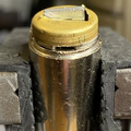
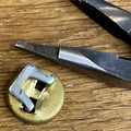
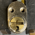
- To remove the brass cap from the rear of the cylinder, take a thin flat head screwdriver and lift the brass cover slightly until the C-clip underneath is exposed. Spread the clip until the legs of the metal U-shaped retainer can be manipulated from under the C-clip, thus freeing the brass cap.
- Remove the C-clip.
- Insert the key and turn the plug 45-90 degrees.
- Withdraw the plug from the cylinder. (A plug follower is recommended)
References
- ↑ "ASSA Catalogue". ASSA. Retrieved 21 February 2023.
- ↑ ASSA product brief: 700-series cylinders (Swedish)


